Fast, repeatable MIG fabrication depends on more than a machine’s maximum amp rating: wire delivery, duty cycle, polarity, gas coverage and tuned settings determine whether the arc stays stable. By the end, you will be able to match machine capacity to your jobs, choose between solid wire and flux-cored wire, set up the equipment correctly and test parameters before production.
Key takeaways
- Match amperage and duty cycle to material thickness and production workload.
- Use wire diameter, shielding gas and settings suited to the base metal.
- Check the liner, contact tip, rollers and gas connections before welding.
- Compare feeder control, thermal protection and service support—not only amp rating.
How a MIG Welding Machine Creates a Consistent Weld
A MIG welding machine feeds a wire electrode through the liner, contact tip and torch. The tip transfers current to the wire; the gap between wire and work creates arc formation and melts both edges. Shielding gas surrounds the arc and molten pool, blocking oxygen and nitrogen.
The work clamp and return cable complete the circuit.
Set wire-feed speed and voltage to keep arc length stable; a worn or oversized contact tip causes wandering, burnback and uneven current transfer. Keep the return clamp on clean metal, use the specified polarity, and maintain gas flow without drafts. A loose ground turns consistent settings into erratic welds.
| Process | Polarity and shielding | Choose it when | Main trade-off |
|---|---|---|---|
| Solid-wire GMAW | Normally electrode-positive; external shielding gas | Indoor fabrication, clean steel and controlled, low-cleanup work | Gas supply and wind protection are required |
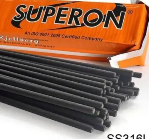
| Flux-cored welding | Self-shielded FCAW commonly uses electrode-negative; gas-shielded FCAW uses external gas | Outdoor work, wind exposure or higher deposition | More smoke, spatter and slag cleanup |
Choose solid-wire GMAW for clean indoor fabrication, thin-to-medium steel, low smoke and minimal cleanup. Choose flux-cored wire for outdoor work, wind exposure or higher deposition when a gas cylinder is impractical; remove slag between passes. Check polarity before changing processes: self-shielded FCAW commonly uses electrode-negative, while solid-wire GMAW normally uses electrode-positive. Wrong settings create spatter.
Match Machine Output and Duty Cycle to the Fabrication Job
Choose a machine by its rated welding machine output at the duty cycle your job demands, not by its maximum amperage. A unit advertised as 60% duty cycle at 300 Aат?
is rated under IEC 60974-1 for six minutes of welding and four minutes of cooling within a 10-minute period at a 40 °C ambient temperature.
Check these constraints before selecting it:
- Input voltage and phase must match the available supply.
- Input current must fit the circuit, including breaker and cable capacity.
- Generator compatibility must cover the machine’s starting and continuous load.
- Thermal derating must leave usable output at your workshop temperature and altitude.
A 300-A machine is a poor production choice if the shop cannot supply it or if repeated welds exceed its rated duty cycle. Ratings tested at 25 °C or at a lower amperage do not compare directly with a 40 °C, 60% figure.
| Job | Practical machine choice | Main limitation |
|---|---|---|
| Sheet metal | Lower output with 0.6–0.9 mm wire | Excess current causes burn-through |
| Frames and gates | Medium output with 0.8–1.0 mm wire | Confirm duty cycle for long seams |
| Structural members | Higher output with 1.0–1.2 mm wire | Thick joints may need multiple passes |
| Repairs | Adjustable output and suitable wire range | Work position and joint access control settings |
Wire diameter sets the stable current range and deposition rate. A machine must support the wire, voltage, and feed speed required for the material thickness; a high amp rating alone cannot compensate for the wrong wire size or inadequate supply.
Choose Wire, Gas and Starting Settings by Material Thickness
For mild steel, start with solid wire, electrode-positive polarity (DCEP), and an argon-carbon dioxide mixture. The table gives practical starting points; confirm the wire manufacturer’s chart before production welding.
| Thickness | Wire and gas | Polarity | Voltage | Wire-feed speed | Gas flow |
|---|---|---|---|---|---|
| 0.8–1.2 mm | 0.8 mm solid wire, 75% argon/25% CO2 | DCEP | 17–18 V | 2.5–4.0 m/min | 12–15 L/min |
| 1.5–3 mm | 0.9 or 1.0 mm solid wire, argon-CO2 mixture | DCEP | 18–21 V | 4.0–6.5 m/min | 14–18 L/min |
| 3–6 mm | 1.0 or 1.2 mm solid wire, 100% carbon dioxide or argon-CO2 mixture | DCEP | 20–24 V | 5.0–8.0 m/min | 16–20 L/min |
| 6 mm and above | 1.2 mm solid or gas-shielded flux-cored wire | DCEP | 23–28 V | 6.0–10.0 m/min | 16–20 L/min |
Use self-shielded flux-cored wire outdoors when wind makes gas shielding unreliable; set the machine to electrode-negative polarity and turn off the gas. The wrong polarity produces violent spatter and weak penetration.
Tune on clean scrap of the same thickness. Set 10–12 mm electrode stick-out, make a short bead, then adjust in this order:
- Increase wire-feed speed if the arc lengthens and the wire burns back; decrease it if the wire stubs into the plate.
- Raise voltage for a longer arc and flatter bead; lower it if the arc becomes harsh and spits.
- Change gas flow in 1–2 L/min steps; excessive flow creates turbulence and draws air into the shield.
Set Up the Gun, Spool, Gas System and Wire Feeder Correctly
Arc consistency starts with a straight wire path and an unobstructed gas path, not with higher machine settings. Assemble the system in this order:
1. Fit the spool with its label facing out, confirm the wire diameter, and match the drive-roll groove to it. Release the brake until the spool stops without overspooling.
2. Inspect the liner for kinks, rust, debris and excessive wear. Replace a damaged liner, then cut the liner flush and seat it firmly against the diffuser. A dirty or loose liner increases friction and causes intermittent feeding.
3. Install the correct contact tip for the wire diameter. It must slide over the wire without wobbling; an oversized, worn or contaminated tip causes arc wandering, burnback and uneven current transfer. Keep anti-spatter compound out of the tip bore and gas passages.
4. Thread the wire through the inlet guide, drive rolls and liner. Increase roll pressure only until the wire feeds without slipping; excessive pressure deforms solid wire and raises liner friction. Four-roll feeders improve grip on long runs.
5. Connect the regulator, hose and diffuser, check fittings for leaks, and purge the hose for 5–10 seconds before welding. Keep the nozzle clear of spatter. A blocked nozzle, damaged diffuser or turbulent flow can create porosity even when the flowmeter reads correctly.
6. Keep the MIG torch cable short, straight and gently curved. Sharp bends raise feeding resistance, especially with aluminum; use U-groove rolls, a low-friction liner, the correct tip and minimal curvature for soft wire. Clamp the work return path to clean metal close to the joint.
Select a Production-Ready MIG System, Not Just a High Amp Rating
A production machine needs a qualified parameter set, not merely a 300-amp label. Ask for settings tied to wire type and diameter, shielding-gas composition, polarity, contact-tip size, stick-out, travel speed and joint fit-up; changing gas or wire diameter can invalidate the old voltage and wire-feed settings.
1. Verify input voltage, phase, duty cycle, output range and generator compatibility together. Request the generator’s required kVA and permitted input tolerance; an undersized or unstable generator causes arc fluctuations and nuisance shutdowns.
2. Specify a four-roll wire feeder with correctly sized drive rolls, a short, straight gun cable and adjustable pressure. Excessive pressure deforms solid wire, while poor alignment creates slip and intermittent arc-length changes.
3. For high deposition on suitable flat or horizontal steel, confirm spray transfer capability, an argon-rich gas program and enough current for the selected wire diameter. Spray transfer is hot and fluid, so it is a poor choice for thin sheet or many out-of-position joints.
4. Choose pulsed GMAW when lower average heat input or out-of-position spray-like transfer matters. Require a matched material, wire and gas program with peak current, background current, pulse frequency and arc-length correction controls.
5. For aluminum, look for a spool gun or push-pull system, U-groove rolls, low-friction liner, correct contact tips and minimal cable curvature. For outdoor work, confirm a flux-cored option or wind-control plan instead of relying on shielding gas alone.
Before ordering, ask Impex Engineering & Equipments Co to document these settings for your material, thickness and production joint rather than quoting amperage alone.
Related products
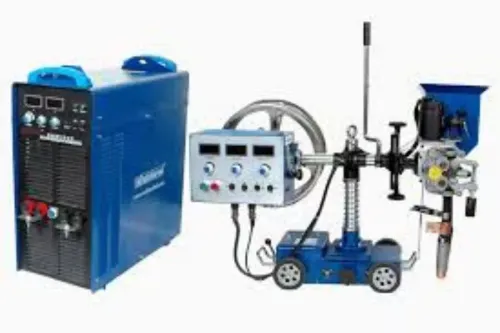
 | Welding Machines Mig-Mag Welding Machines Price And Quantity Price 1 INR/Unit Minimum Order Quantity 1 Mig-Mag Welding Machines Trade Information Supply Ability 1 Per Day Delivery Time 1 Week... |
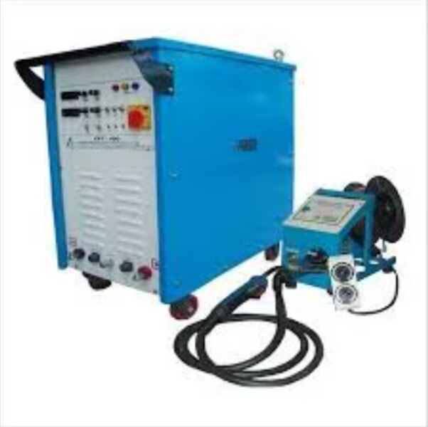
 | Welding Machines Automatic Mig Welder Price And Quantity Minimum Order Quantity 1Price 1 INR/Unit Automatic Mig Welder Trade Information Supply Ability 1 Per DayDelivery Time 1 Week... |
Frequently asked questions
How does a MIG welding machine create a consistent weld?
It continuously feeds a wire electrode through the liner, contact tip and torch while shielding gas protects the arc and molten pool from oxygen and nitrogen.
How do you match MIG output and duty cycle to a fabrication job?
Choose output based on material thickness, joint design and wire size, then select a duty cycle that covers the machine’s expected welding time without overheating.
How do you choose MIG wire, gas and settings by material thickness?
Select wire diameter and shielding gas for the base metal and thickness, then set voltage, wire-feed speed and gas flow through trial welds and manufacturer guidance.
What should you check when setting up a MIG welding system?
Inspect the gun liner, contact tip, drive rollers, spool, polarity, regulator, hose connections and wire-feed tension before starting.
What features matter in a production-ready MIG welding system?
Evaluate duty-cycle performance, stable wire feeding, control range, thermal protection, torch ergonomics, spare-part availability and service support alongside amp rating.