A pressure-tight seam depends on more than running two copper wheels along an overlap: current, force, speed and pulse spacing determine whether the nuggets overlap or leave leak paths. By the end, you will be able to distinguish seam-welding modes, match a machine to your component, and define a schedule that can be tested rather than accepted on the machine’s nominal rating.
Key takeaways
- Use wheel speed, current time and weld time to control nugget spacing.
- Specify sheet thickness, overlap, material and joint length before choosing a machine.
- Water-cooled electrode wheels limit overheating and maintain consistent contact resistance.
- Verify weld pitch, peel strength, leak tightness and the approved weld schedule.
How rotating electrode wheels form a seam
Resistance seam welding, ISO 4063 process 23, joins overlapping sheets between two rotating copper-alloy electrode wheels. The wheels apply electrode force while welding current crosses the contact area; resistance heating creates individual weld nuggets between the sheets.
Wheel speed and weld time set nugget spacing and overlap, so a smooth, continuous-looking line is not automatically a continuously molten fusion bead.
| Mode | Current pattern | Best use |
|---|---|---|
| Continuous seam welding | Current remains applied as the wheels travel | Pressure-tight tanks, drums and ducts when heat can be controlled |
| Intermittent seam welding | Programmed weld and off periods produce overlapping nuggets | Sealed joints with lower average heat input and less electrode wear |
| Roll-spot welding | Rotating wheels make programmed, closely spaced spot welds | Mechanical joints or controlled sealing where full continuity is unnecessary |
| Stitch welding | Separate spot welds leave deliberate gaps | Structural attachment where leakage is not a requirement |
| Conventional spot welding | Stationary electrodes make isolated nuggets | Discrete mechanical joints at selected locations |
Choose the mode from the joint’s job. A mechanical joint needs enough nugget size and spacing to carry load; a pressure-tight joint needs sufficient overlap to remove open leak paths. Continuous mode supplies heat throughout travel, while intermittent and roll-spot modes reduce average heat input through programmed weld and off periods.
If their pitch is too wide, the gaps leak; if overlap is excessive, heat accumulates and current shunts through earlier nuggets.
How weld pattern and pitch control heat and leak paths
Choose a continuous seam weld for a pressure-tight path; choose intermittent seam welding when heat input and distortion matter more than uninterrupted sealing; choose overlapping spot welds for a mechanical joint with defined load points.
| Pattern | Heat and leak result | Suitable use |
|---|---|---|
| Continuous seam weld | Highest average heat; no programmed leak gaps | Pressure or fluid containment |
| Intermittent seam welding | Lower average heat; pitch must overlap nuggets | Long joints where distortion is a risk |
| Overlapping spot welds | Discrete nuggets with controlled overlap | Mechanical attachment without full sealing |
Weld pitch is the distance between nugget centres. Excessive pitch leaves an unsealed path between nuggets; excessive overlap increases heat accumulation, electrode wear and current shunting. Shunting draws current through earlier nuggets, close parallel seams, conductive fixtures or narrow edge distances instead of the active contact.
Set welding current, electrode force, wheel speed, weld time, off time and squeeze time as one schedule. Increasing wheel speed without increasing current or pulse duration lowers heat input per unit length and can produce undersized or intermittent nuggets.
Too little force promotes expulsion and pickup; too much enlarges the contact area, lowers current density and can suppress nugget growth.
Control the fit-up before setting current:
- Limit gaps, waviness and overlap variation; they redistribute force.
- Remove burrs, oil and scale; each changes contact resistance.
- Prevent fixture deflection; movement changes force during welding.
- Recheck edge distance and parallel seams on production parts, not only coupons.
A schedule proven on a flat coupon can leak on a distorted assembly.
How to specify the machine for your part
Specify the machine from the part’s thickness, material and geometry—not its maximum advertised kVA. Record these inputs before comparing quotations:
| Machine configuration | Travel and workholding | Use |
|---|---|---|
| Longitudinal seam welding machine | Wheels travel along the component | Straight seams in tanks, ducts or panels |
| Transverse seam welding machine | Wheels cross the component | Seams across formed sheets or strips |
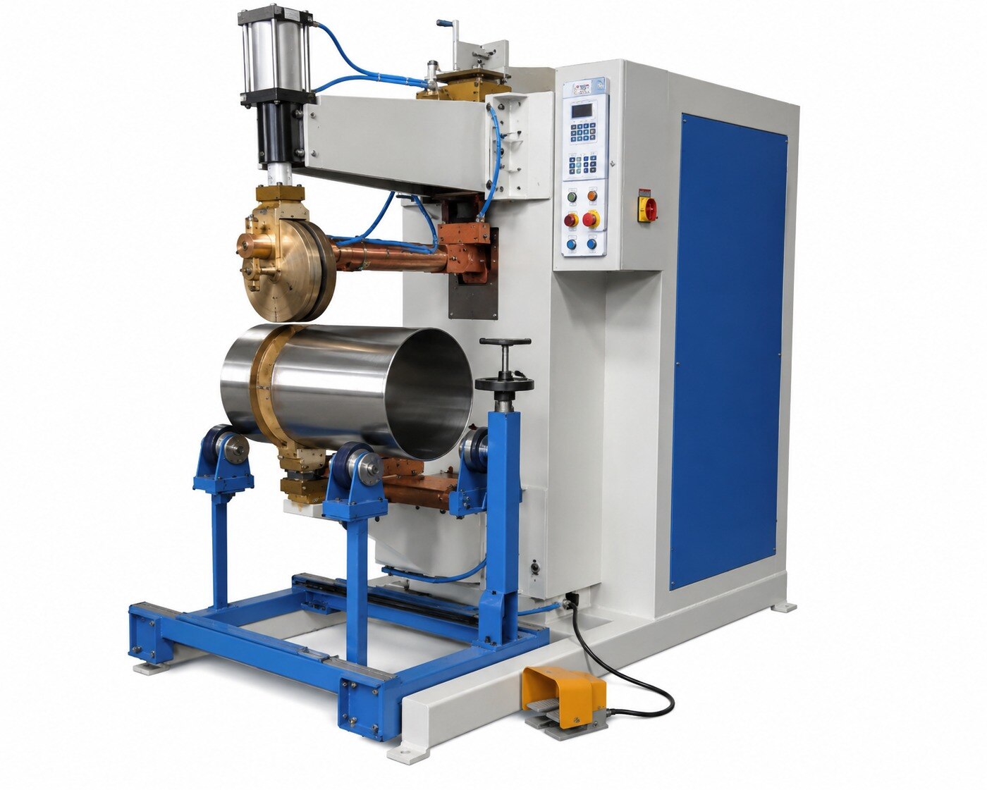
| Circumferential seam welding | The part rotates while the wheels weld around it | Cylindrical shells, drums and pipes |
Match the thickness range, material grade, galvanized or other coating, overlap, required weld length and cycle time. Compare single-phase supply with a three-phase seam welder, then check transformer rating at the required duty cycle, available short-circuit current, electrode-force range and controller pulse resolution.
Specify electrode-wheel diameter and profile as well as wheel-face width. Effective weld width depends on that face, sheet overlap, edge distance and current-path location; excessive overlap can restrict access or encourage shunting.
Nominal throat depth does not prove the wheel will reach a formed flange, return, stiffener or other obstruction. Check the actual workpiece in the throat, including fixture clearance and wheel approach.
Give Impex Engineering & Equipments Co these details for a meaningful configuration check:
- Part drawings and sample components
- Material grades, coatings and thicknesses
- Overlap and edge-distance dimensions
- Weld length, travel direction and cycle time
- Required force, cooling arrangement and production duty cycle
A supplier cannot validate access or thermal capacity from sheet thickness alone.
How electrode wheels and water cooling affect production
A copper-alloy electrode wheels transfers welding current and clamping force into the overlap. A wider face spreads force over more area, lowers current density, and changes nugget growth; specify it when the sheet, overlap, and required weld width demand that distribution.
A profiled face follows an overlap or formed part, but concentrates force and current, so the electrode-wheel profile and alignment must match the component.
Use this production checklist:
- Perform wheel dressing to remove zinc or material pickup and restore the working profile.
- Keep both wheels parallel; misalignment creates uneven pressure, current paths, indentation, and premature wear.
- Replace a wheel when dressing leaves it undersized, the face is cracked or badly grooved, or the profile no longer reaches the joint correctly.
- Treat zinc pickup on galvanized sheet as a process fault: it raises contact instability, fouls the interface, and requires cleaning plus a controlled force-and-current schedule.
- Inspect water cooling flow, inlet temperature, blocked passages, leaks, hose condition, and wheel-to-workpiece contact.
- Confirm cooling reaches the transformer and welding head, not only the electrode wheels.
Insufficient water cooling lets wheel temperature rise during the run, causing pickup, unstable current transfer, rapid wear, and progressive weld-quality loss. Coating vaporization adds contamination; provide suitable extraction and clean the wheel interface and nearby guards before deposits alter contact. Stop production for a cooling fault rather than compensating with higher current.
How to verify the weld schedule and joint performance
Turn the machine rating into a controlled seam welding schedule by recording welding current, electrode force, wheel speed, squeeze time, weld time and off time for each qualified part.
1. Set the schedule against the actual material, thickness, overlap and weld length. Verify current and force using the machine’s current measurement, force measurement or calibration records; a controller setpoint alone does not prove that the secondary circuit delivered the intended values.
2. Control run-on and run-off at both ends of the joint. Use lead-in and lead-out material, programmed current ramps or overlap so the first and last nuggets reach size without expulsion or a short unsealed section.
Increasing wheel speed without increasing current or weld time reduces heat input per unit length and can create intermittent or undersized nuggets.
3. Qualify the procedure under ISO 15614-12 for the applicable spot, seam or projection welding process. Test representative material grades and thickness ranges, then record the essential variables and examination results so production changes can be judged against the qualified range.
4. Check every production run for fit-up, wheel condition, cooling flow, measured current and electrode force. Use destructive sectioning or peel-type evaluation as appropriate, and perform a leak test when the component contains fluid or gas.
A smooth, continuous surface line cannot reveal every internal lack-of-overlap, pore or shunting-related weak zone. Joint performance requires evidence from the specified tests, not appearance alone.
Frequently asked questions
How do rotating electrode wheels create a continuous seam?
The wheels apply force and carry welding current through overlapping sheets while rotating. Resistance heating creates successive weld nuggets along the joint.
How do weld pattern and pitch affect a seam weld?
Continuous, intermittent and stitch patterns place nuggets differently. Pitch controls nugget overlap, heat input and the leak paths that can remain between welds.
What information is needed to specify a seam welding machine?
Provide sheet material, thickness range, overlap, joint geometry, seam length, required pattern, production rate and available electrical supply.
Why do electrode wheels need water cooling?
Cooling removes heat from the wheels, stabilises electrode contact and reduces distortion, sticking and premature wheel wear during production.
How do you verify seam-welded joint performance?
Check the weld schedule, nugget spacing, visual defects, peel or tensile results and leak tightness using a test method suited to the component.