A production spot weld is controlled by much more than a machine’s advertised amperage: current, time, force, electrode condition, material and weld spacing interact at every joint. By the end, you will be able to map the weld cycle, specify machine capacity, choose suitable electrodes and build checks that keep nugget quality stable as production volume rises.
Key takeaways
- Size the machine for sheet thickness, weld schedule and required electrode force.
- Use clean, correctly shaped electrode tips to maintain current density.
- Verify nugget size, penetration and joint strength before increasing production.
- Compare power ratings by duty cycle, not maximum output alone.
How resistance spot welding forms a nugget
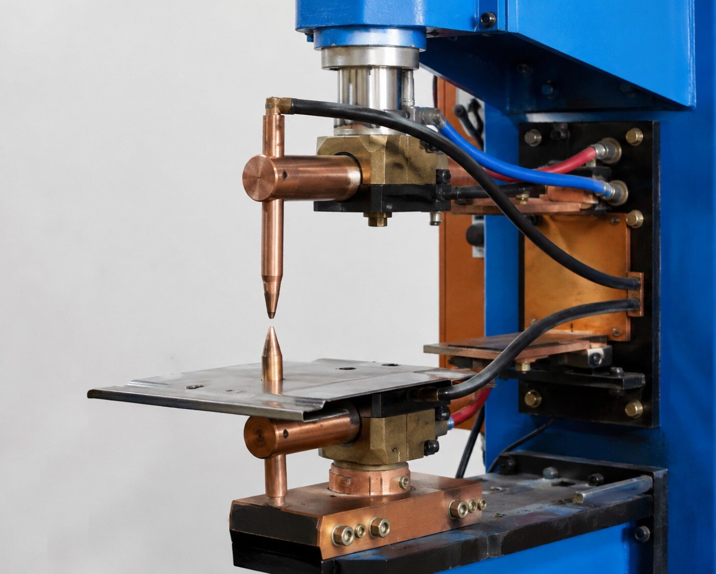
Two copper-alloy electrode caps clamp overlapping sheets and establish the specified force before current flows. In resistance spot welding, current travels through the upper sheet, faying interface and lower sheet before returning through the circuit. Electrical resistance converts energy into heat according to Q = I²Rt.
Heat concentrates at the interface, forming a molten weld nugget while the surrounding metal remains solid.
1. During squeeze time, the electrodes close and reach the programmed force. The controller must not apply current before that force is established; early firing creates unstable contact, inconsistent heating and expulsion.
2. During weld time, current passes through the stack and melts a small zone at the faying interface. The nugget grows until current stops or the schedule reaches its limit.
3. During hold time, the electrodes stay closed while the nugget solidifies. This containment reduces cracks, shrinkage defects and distortion, then the caps release.
4. During off-time, the part indexes to the next location. Repeatable indexing prevents missed or crowded weld positions, while controlled electrode opening allows fast loading without striking the sheet or delaying the cycle.
5. Check the real assembly for current shunting. A nearby completed weld, flange, fixture or other conductive path can bypass current from the intended spot, especially at close pitch.
A schedule proven on an isolated coupon can therefore deliver less current at later production welds, so stable force, cap alignment and cycle timing matter across hundreds or thousands of repetitions.
How to size capacity for the actual joint
A capacity check starts with the complete stack-up, not the machine’s peak amperage. Record sheet thickness, material grades, number of sheets, coatings, surface condition, flange fit-up and contamination.
1. Set the joint target. For many low-carbon-steel joints, estimate minimum nugget diameter with d ≈ 4√t, where t is the thinner sheet thickness in millimetres. Treat this as a design or acceptance rule, not a universal setting. Confirm the required weld diameter, weld pitch or spacing, loading mode and customer welding standard.
2. Measure access. Specify the maximum distance from the machine throat to the joint, then check throat depth, arm geometry, cap access and maximum electrode travel. A short throat can reject a machine with adequate electrical capacity because the caps cannot reach the weld.
3. Match force and schedule. Confirm maximum electrode force and force-control repeatability. In Q = I²Rt, current has a squared effect on heat, while resistance and weld time act approximately linearly.
Excessive current causes expulsion, craters, electrode damage and a smaller retained nugget; insufficient force creates unstable contact, while excessive force suppresses interface heating and deepens indentation.
4. Validate the process window. At the specified force, plot current against weld time in a weld-lobe diagram. The lower boundary produces an acceptable nugget; the upper boundary is limited by expulsion, burn-through, sticking or excessive indentation. Stack-up and loading changes can move both limits.
Specify capacity at the actual joint, not on an isolated coupon or nominal amperage alone.
How power systems and ratings affect production output
Power arrangement affects production output through current delivery, heat control and supply demand—not amperage alone.
| Arrangement | How it delivers power | Production implication |
|---|---|---|
| single-phase AC | Pulsed current directly from the supply | Greater input-demand fluctuations; suitable only when the site supply and cycle rate support them |
| three-phase AC | Shares the electrical load across three phases | More even loading for higher production demand when the available supply supports it |
| MFDC | A high-frequency inverter and transformer rectification deliver DC at the secondary | More uniform control and lower transformer and cable mass for a given application |
| capacitor-discharge spot welder | Stores energy and releases a short pulse | Limits overall heat input, but energy capacity and repetition rate must match the work |
MFDC still needs the correct secondary current, electrode force, weld time, cooling and duty cycle. A capacitor-discharge spot welder is unsuitable when its stored energy cannot maintain the required nugget or repetition rate.
Compare these ratings before choosing a machine:
- Transformer rating in kVA and nominal secondary-current range
- Transformer and gun duty cycle at the intended cycle rate
- Controller resolution, maximum electrode force and force-control repeatability
- Throat depth, arm and cap geometry, and cooling-water demand
Confirm input voltage, frequency, phase arrangement, breaker capacity and cable installation with the site electrician. High kVA does not prevent overheating, poor access or a failed joint when the gun, throat or arms are unsuitable. Ask for rated output at the intended duty cycle, not a detached peak-current figure.
How electrodes and tip maintenance control current density
A worn electrode cap enlarges the contact area, lowers current density, and can turn a sound weld schedule into a small, inconsistent nugget. Electrode materials and tip geometry must match the sheet because copper-alloy caps are consumable process tooling, not permanent machine parts.
1. For low-carbon steel, use copper-alloy electrodes with a flat, truncated-cone or domed tip. Select the shape for access, required indentation and current concentration.
2. Set stainless steel schedules and tip geometry to limit sticking and surface marking. Excessive heat at the face can transfer material and destabilise the next weld.
3. Galvanised steel needs coating-specific current and force settings. Zinc changes initial contact resistance and accelerates face alloying, so do not copy bare-steel parameters onto zinc-coated sheet. Control coating damage and remove oil, dirt and other surface contamination before welding.
4. Aluminium needs much higher current, shorter weld time and carefully controlled force. Use electrode materials and cooling arrangements that tolerate rapid face degradation; a steel schedule is not a valid starting point.
5. Inspect caps by weld count and production volume. On a high-volume line, set a count-based check for every shift or batch; extend the interval only after trial data proves tip growth stays inside the process window. Perform tip dressing or replace the cap for tip mushrooming, pitting, zinc pickup, asymmetric wear or contamination.
Misalignment changes current density and indentation. Raising current to compensate for worn caps increases expulsion and shortens electrode life, so restore tip condition before changing the schedule.
How to verify weld quality before scaling production
Prove reliability on the production assembly, not on a coupon alone. Run a controlled trial that includes flange gaps, fit-up, galvanising mass, contamination, sheet variation, electrode alignment and current shunting from nearby welds; each can move an unchanged schedule outside its weld lobe.
1. Verify part presence and electrode force before firing. Record secondary current or dynamic resistance for every cycle. Add expulsion detection through electrode displacement, acoustic signals or optical sensing when the risk justifies it. These systems flag abnormal cycles; they do not replace destructive validation.
2. Audit the joint with a peel test and chisel test. They expose undersized nuggets, interfacial failure and welds that separate without pulling a plug from the parent sheet. Use a cross-tension test or tensile-shear test when those results match the joint’s service loading.
3. Inspect indentation, spatter and electrode marks, but do not accept a neat-looking indentation as proof of an adequate nugget. Destructive results decide acceptance.
4. Give Impex Engineering & Equipments Co the application data before comparing a spot welding machine: material and thickness stack-up, nugget target, weld pitch, access dimensions, electrode force, cycle rate, cooling arrangement and input supply. Ask for secondary-current range, force-control repeatability, duty-cycle data and a demonstration on representative parts.
5. Record tip counts, test results, failed locations and corrective actions. Revalidate after changes to sheet, coating, fit-up or weld sequence, because a coupon can hide access problems and current shunting.
Frequently asked questions
How does resistance spot welding form a nugget?
Copper-alloy electrodes clamp overlapping sheets, then current passes through the joint. Resistance converts electrical energy into heat, forming a molten weld nugget at the faying interface.
How do you size a spot welding machine for the actual joint?
Match the machine to sheet thickness, material, overlap, electrode force, weld schedule and the required production rate rather than selecting by maximum current alone.
How do power systems and ratings affect production output?
Power-system design, available current, weld-time control and duty cycle determine how quickly the machine completes welds and recovers between cycles.
How do electrode tips control current density?
Correct tip material, alignment, contact area and dressing keep current concentrated at the joint. Worn or contaminated tips spread current and reduce weld consistency.
How do you verify spot weld quality before scaling production?
Run sample welds, inspect nugget formation and penetration, and test joint strength against the production specification before increasing output.